


Plastic anchor for frames W-UR F 8, galvanised steel
Plastic frame anchor W-UR F 8 steel zp hex. head
ANC-(W-URF8)-PLA-AW25-WS10-50/30-8X100
Art.-no. 0912808604
EAN 4047376505421


Register now and access more than 125,000 products
- With galvanised steel hexagon head bolt and lock washer
- Can be installed directly
- Immediate load capacity, no waiting
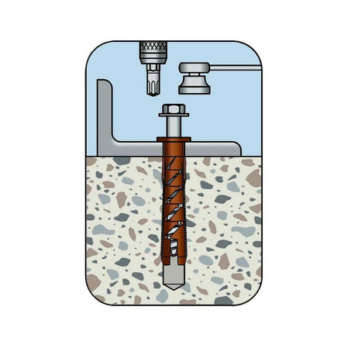
- Low anchor screw insertion torque; "slight" anchor expansion with virtually no movement of the anchor sleeve
- 2 insertion depths (hnom = 50 + 70 mm): Concrete >= C12/15; solid brick >= Mz 10 (>= NF); vertically perforated brick >= HLz 8 (>= 2DF); solid sand-lime brick >= KS 10 (>= NF); hollow sand-lime brick >= KS L 6 (>= 2DF); hollow sand-lime brick >= KS L 6 (>= 12DF); solid blocks of standard concrete >= Vbn 10 (>= NF); solid lightweight concrete blocks ,>= V 2 (>= NF)
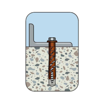
- Expands in four directions: high load-bearing capacity
- Increased force transmission: Even, continuous load distribution across the entire expansion area
- Universal frame fixing (concrete, perforated brick, solid brick, masonry and autoclaved aerated concrete)
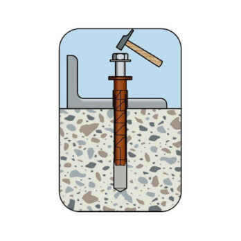
- Hammer-in stop prevents premature expansion during installation
- Special pre-assembled anchor and screw for easier installation
- Type W-UR F anchor does not require an additional U-washer and prevents contact corrosion
- Improved load transfer in solid and hollow construction materials; anchorage via friction locking between anchor sleeve and anchoring base
W-UR 8, W-UR F8 (galvanised steel, stainless steel): General building permit Z-21.2-1838
W-UR 8 and W-UR F 8 (galvanised steel, stainless steel): European technical approval ETA-08/0190
Anchor sleeve made of high-quality polyamide
Fire resistance W-UR 8: Concrete: Tensile and transverse loads, R30, R60, R90, R120 (according to technical report TR 020) Masonry tensile load: F30 (solid sand-lime brick, solid brick, hollow sand-lime brick) Transverse load: F30, F60, F90, F120 (hollow brick, hollow sand-lime brick, solid brick, autoclaved aerated concrete)
Notice:
Drill perforated and hollow blocks with a rotary drill (without impact mechanism)
For anchoring in solid brick and solid sand-lime brick, we recommend that you perform pull-out tests due to the differences in brick manufacturing.
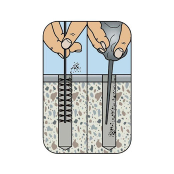
Drill cuttings must be removed from the drill hole
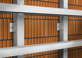 Metal substructures
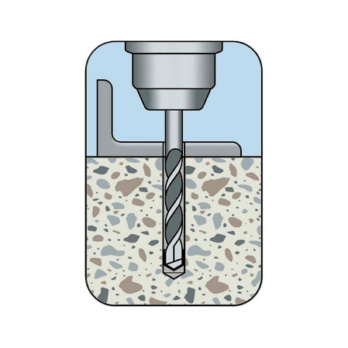
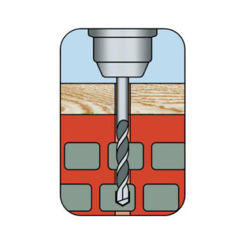 Create the drill hole
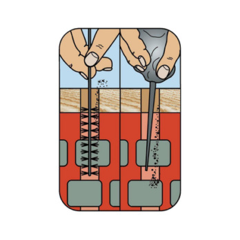 Clean the drill hole
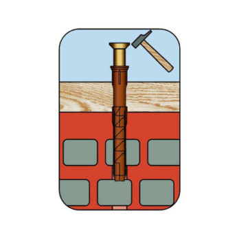 Set anchor and screw
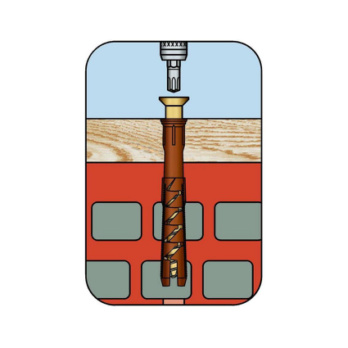 Screw in the screw
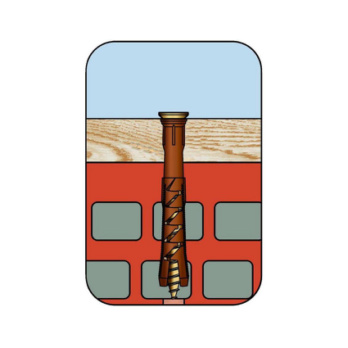 Screw in screw until flush
 Create the drill hole
 Clean the drill hole
 Set anchor and screw
 Screw in the screw
 Screw in screw until flush
Datasheets(X)

The anchor has European technical approval for use in multiple connections of non-load-bearing systems (e.g. frames, suspended ceilings etc.).
W-UR and W-UR F can be anchored in the following anchor bases: Standard concrete, masonry walls (solid brick, solid sand-lime brick, vertically perforated brick, hollow sand-lime brick, hollow lightweight concrete blocks, solid bricks and solid lightweight concrete blocks, concrete bricks, autoclaved aerated concrete), brick ceilings, prestressed hollow concrete slabs, reinforced autoclaved aerated concrete, plasterboard wall panels
Installation temperatures:
Anchor base temperature: >= -40 °C
Anchor sleeve temperature: >= 0 °C
The galvanised screw can be used outdoors or in damp spaces (with careful installation) if the area around the screw head is protected from moisture or rain, so moisture does not penetrate the anchor shaft (suitable paint)
Ideal for attaching facades, ceilings and ceiling substructures (made of wood or steel), wooden beams, wooden slats, metal brackets, metal rails, suspended ceilings, cable ducts, brackets, profiles, wall-mounted cabinets, shelves etc.
Anchor diameter | 8 mm |
Anchor length (l) | 100 mm |
Nominal drill-bit diameter (d 0) | 8 mm |
Through-hole in the component to be connected (d f) | 8.5 mm |
Attachment height (t fix 1) | 50 mm |
Material of screw | Steel |
Internal drive | AW25 |
Surface of the screw | Zinc plated |
Head type | Hexagon head |
Approval | ETA-08/0190 |
Type description | W-UR F 8, hexagonal bolt |
| Characteristic fitting values for concrete and masonry | ||||
| Anchor diameter [mm] | W-UR 8 | |||
| Nominal drill diameter | d0 [mm] | 8 | ||
| Drill depth | dcutting ≤ [mm] | 8,45 | ||
| Drill depth | h1 ≥ [mm] | 607) | 80 | |
| Insertion depth of the anchor sleeve | hnom [mm] | 507) | 70 | |
| Through-hole in the attachment | df ≤ [mm] | 8,5 | Concrete: ETA-08/0190, attachment of various systems without load-bearing | |
| Anchor diameter [mm] | W-UR 8 | |||
| Central tensile load1) for single anchors or groups of anchors | Nperm = C12/15 [kN] | 30 °C2)/50 °C3) | 1,2 | 1,6 |
| 50 °C2)/80 °C3) | 1,0 | 1,4 | ||
| Nperm ≥ C16/20 [kN] | 30 °C2)/50 °C3) | 1,6 | 2,4 | |
| 50 °C2)/80 °C3) | 1,4 | 2,0 | ||
| Shear stress1) A4 stainless steel For single anchors or groups of anchors | Vperm ≥ C12/15 [kN] | 3,37 | 3,37 | |
| 1) The partial safety factors of the resistances regulated in the approval and a partial safety factor of the effects of γF = 1.4 have been taken into account. Please refer to the European Technical Approval Guidelines (ETAG) 020, Appendix C, for information on combining tensile and transverse loads. 2) Long-term maximum temperature. 3) Short-term maximum temperature. 7) 2. Placement depth responds to the following anchoring reasoning: Concrete ≥ C12/15; solid brick ≥ Mz 10 (≥ NF); vertically perforated brick ≥ HLz 8 (≥ 2DF); solid sand-lime brick ≥ KS 10 (≥ NF); perforated sand-lime brick ≥ KS L 6 (≥ 2DF); perforated sand-lime brick ≥ KS L 6 (≥ 12DF); solid brick of standard concrete ≥ Vbn 10 (≥ NF); solid lightweight concrete brick ≥ V 2 (≥ NF) | ||||
| Anchor dimensions | |||||||
| Anchor diameter | [mm] | W-UR 8 | |||||
| Total length | l [mm] | 60 | 80 | 100 | 120 | 140 | 160 |
| Max. attachment height, hnom= 50 mm7) | tfix [mm] | 107) | 307) | 507) | 707) | 907) | 1107) |
| Max. attachment height, hnom= 70 mm | tfix [mm] | - | 10 | 30 | 50 | 70 | 90 |
| 7) 2. Placement depth responds to the following anchoring reasoning: Concrete ≥ C12/15; solid brick ≥ Mz 10 (≥ NF); vertically perforated brick ≥ HLz 8 (≥ 2DF); solid sand-lime brick ≥ KS 10 (≥ NF); perforated sand-lime brick ≥ KS L 6 (≥ 2DF); perforated sand-lime brick ≥ KS L 6 (≥ 12DF); solid brick of standard concrete ≥ Vbn 10 (≥ NF); solid lightweight concrete brick ≥ V 2 (≥ NF) | |||||||
| Masonry4): ETA-08/0190, attachment of various non-load-bearing systems (temperature range: 50 °C2)/80 °C3))For information on other stone types, apparent densities and minimum compressive strengths, please refer to approval document ETA-08/0190. | |||||
| Brick size [mm] | Apparent density class [kg/dm³] | Minimum compressive strength [N/mm²] | Fperm. [kN]5) (for single anchors or groups of anchors) W-UR 8 hef= 50 to 69 mm/hef= 70 mm | ||
| Brick Mz, EN 771-1, DIN 105 | ≥ NF (≥ 240 x 115 x 71) | ≥1.8 | 28 | 0,71 | 0,86 |
| 36 | 1,0 | 1,14 | |||
| Solid sand-lime brick KS, EN 771-2, DIN 106 | ≥ NF (≥ 240 x 115 x 71) | ≥ 2.0 | 10 | 0,43 | 0,43 |
| 20 | 0,57 | 0,71 | |||
| 28 | 0,86 | 1,0 | |||
| Solid brick of normal concrete Vbn, EN771-3, DIN 18152 | ≥ NF (≥ 240 x 115 x 71) | ≥ 2.0 | 10 | 0,43 | 0,43 |
| 20 | 0,71 | 0,71 | |||
| 28 | 1,0 | 1,0 | |||
| Vertically perforated brick HLz6), EN 771-1, DIN 105-1 e.g. Wienerberger, Schlagmann | ≥ 2DF (≥ 240 x 115 x 113) | ≥ 1.2 | 8 | 0,14 | 0,21 |
| 12 | 0,21 | 0,26 | |||
| 20 | 0,34 | 0,43 | |||
| Vertically perforated brick POROTON S11-36.56), EN 771-1, Z-17.1-812 Wienerberger, Schlagmann | ≥ 248 x 365 x 249 | ≥ 0.9 | 6 | - | 0,57 |
| UNIPOR WS14 vertically perforated brick, UNIPOR WS12 CORISO EN 771-1, Z-17.1-883 Unipor-Ziegel Marketing GmbH | ≥ 10DF (≥ 247 x 300 x 249) | ≥0.8 | 10 | - | 0,17 |
| 12 | - | 0,21 | |||
| Vertically perforated brick KSL6), EN 771-2, DIN 106-1 e.g. Xella | ≥ 2DF (≥ 240 x 115 x 113) | ≥ 1.6 | 10 | 0,26 | 0,57 |
| 12 | 0,26 | 0,71 | |||
| 16 | 0,34 | 0,71 | |||
| ≥ 8DF (≥ 249 x 240 x 238) | ≥1.4 | 10 | - | 0,26 | |
| 12 | - | 0,34 | |||
| 16 | - | 0,43 | |||
| Hollow lightweight concrete block 3K Hbl, EN 771-3, DIN 181516) e.g. Liapor | ≥ 16DF (≥ 498 x 240 x 238) | ≥ 0.7 | 2 | - | 0,11 |
| 4 | - | 0,26 | |||
| 6 | - | 0,34 | |||
| Hollow lightweight concrete brick Liapor-Super-K6), EN 771-3, Z-17.1-501 | ≥ 16DF (≥ 495 x 240 x 238) | ≥0.8 | 2 | - | 0,17 |
| 4 | - | 0,34 | |||
| Autoclaved aerated concrete AAC | 2 | - | 0,14 | ||
| 7 | - | 0,85 | |||
| 2) Long-term maximum temperature. 3) Short-term maximum temperature. 4) For information on other stone types, apparent densities and minimum compressive strengths, please refer to approval document ETA-08/0190. 5) The geometry of the stones must be compared with the provisions of approval ETA-08/0190. 6) If drilling is carried out by impact or hammering, the permissible load must be calculated by carrying out checks on the structure. | |||||